|
| Information | |||
INJECTION MOLD P5 3 1 Mold DesignsMolds used for injection molding of thermoplastic resins are usually flash molds, because in injection molding, as in transfer molding, no extra loading space is needed. However, there are many variations of this basic type of mold design. The design most commonly used for all types of materials is the two plate design (FIGURE PP.9). The cavities are set in one plate, the plungers in the second plate. The sprue blushing is incorporated in that plate mounted to the stationary half of the mold. With this arrangement it is possible to use a direct center gate that leads either into a single-cavity mold or into a runner system for a multi-cavity mold. The plungers are ejector assembly and, in most cases, the runner system belongs to the moving half of the mold. This is the basic design of an injection mold, though many variations have been developed to meet specific requirements. A three-plate mold design (FIGURE PP.10) features a third, movable, plate which contains the cavities, thereby permitting center or offset gating into each cavity for multicavity operation. When the mold is opened, it provides two openings, one for ejection of the molded part and the other for removal of the runner and sprue. Moldings with inserts or threads or coring that cannot be formed by the normal functioning of the press require installation of separate or loose details or cores in the mold. These loose members are ejected with the molding. They must be separated from the molding and reinstalled in the mold after every cycle. Duplicate sets are therefore used for efficient operation. Hydraulic or pneumatic cylinders may be mounted on the mold to actuate horizontal coring members. It is possible to mold angular coring, without the need for costly loose details, by adding angular core pins engaged in sliding mold members. Several methods may be used for unscrewing internal or external threads on molded parts: For high production rates automatic unscrewing may be done at relatively low cost by the use of rack-and-gear mechanism actuated by a double-acting hydraulic long-stroke cylinder. Other methods of unscrewing involve the use of an electric gear-motor drive or friction-mold wipers actuated by double-acting cylinders. Parts with interior undercuts can be made in a mold which has provision for angular movement of the core, the movement being actuated by the ejector bar that frees the metal core from the molding.
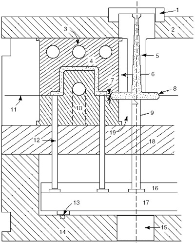
FIGURE PP.9 A two-plate injection-mold design: (1) locating ring; (2) clamping plate; (3) water channels; (4) cavity; (5) sprue bushing; (6) cavity retainer; (7) gate; (8) full round runner; (9) sprue puller pin; (10) plunger; (11) parting line; (12) ejector pin; (13) stop pin; (14) ejector housing; (15) press ejector clearance; (16) pin plate; (17) ejector bar; (18) support plate; (19) plunger retainer. |
|||
|