|
| Information | |||
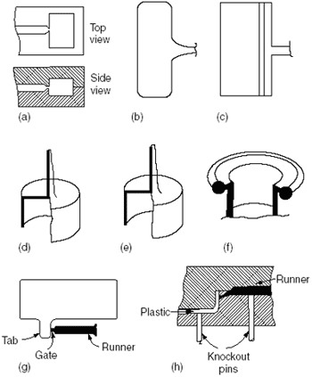
INJECTION MOLD P5 3 4 GatingThe gate provides the connection between the runner and the mold cavity. It must permit enough material to flow into the mold to fill out the cavity. The type of the gate and its size and location in the mold strongly affect the molding process and the quality of the molded part. There are two types of gates: large and restricted. Restricted (pinpointed) gates are usually circular in cross section and for most thermoplastics do not exceed 0.060 in. in diameter. The apparent viscosity of a thermoplastic is a function of shear rate梩he viscosity decreases as the shear rate and, hence, the velocity increases. The use of the restricted gate in therefore advantageous, because the velocity of the plastic melt increases as it is forced through the small opening; in addition, some of the kinetic energy is transformed into heat, raising the local temperature of the plastic and thus further reducing its viscosity. The passage through a restricted area also results in higher mixing. The most common type of gate is the edge gate (FIGURE PP.11a), where the part is gated either as a restricted or larger gate at some point on the edge. The edge gate is easy to construct and often is the only practical way of gating. It can be fanned out for large parts or when there is a special reason. Then it is called a fan gate (FIGURE PP.11f).When it is required to orient the flow pattern in one direction, a flash gate (FIGURE PP.11c) may be used. It involves extending the fan gate over the full length of the part but keeping it very thin. The most common gate for single-cavity molds is the sprue gate (FIGURE PP.11d). It feeds directly from the nozzle of the machine into the molded part. The pressure loss is therefore a minimum. But the sprue gate has the disadvantages of the lack of a cold slug, the high stress concentration around the gate area, and the need for gate removal. A diaphragm gate (FIGURE PP.11e) has, in addition to the sprue, a circular area leading from the sprue to the piece. This type of gate is suitable for gating hollow tubes. The diaphragm eliminates stress concentration around the gate because the whole area is removed, but the cleaning of this gate is more difficult than for a sprue gate. Ring gates (FIGURE PP.11f) accomplish the same purpose as gating internally in a hollow tube, but from the outside.
FIGURE PP.11 Gating design: (a) edge; (b) fan; (c) flash; (d) sprue; (e) diaphragm; (f) ring; (g) tab; (h) submarine. When the gate leads directly into the part, there may be surface imperfection due to jetting. This may be overcome by extending a tab from the part into which the gate is cut. This procedure is called tab gating (FIGURE PP.14g). The tab has to be removed as a secondary operation. A submarine gate (FIGURE PP.11h) is one that goes through the steel of the cavity. It is very often used in automatic molds. |
|||
|