|
| Information | |||
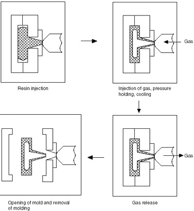
INJECTION MOLD P5 6 Gas Assisted Injection MoldingThe gas-assisted injection molding process begins with a partial or full injection of polymer melt into the mold cavity. Compressed gas is then injected into the core of the polymer melt to help fill and pack the mold, as shown in FIGURE PP.15 for the Asahi Gas Injection Molding process. This process is thus capable of producing hollow rigid parts, free of sink marks. The hollowing out of thick sections of moldings results in reduction in part weight and saving of resin material. Other advantages include shorter cooling cycles, reduced clamp force tonnage and part consolidation. The process allows high precision molding with greater dimensional stability by eliminating uneven mold shrinkage and makes it possible to mold complicated shapes in single form, thus reducing product assembly work and simplifying mold design. The formation of thick walled sections of a molding can be easily achieved by introducing gas in the desired locations. The gas channels thus formed also effectively support the flow of resin, allowing the molding pressure to be greatly reduced, which in turn reduces internal stresses, allows uniform mold shrinkage, and reduces sink marks and warpage.
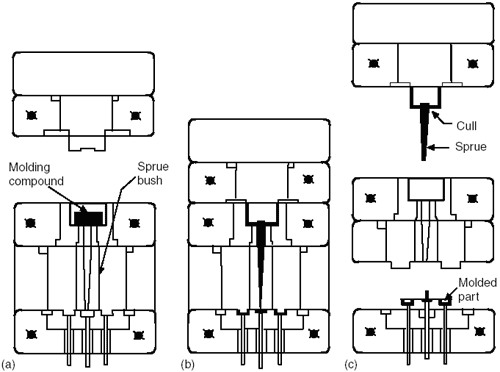
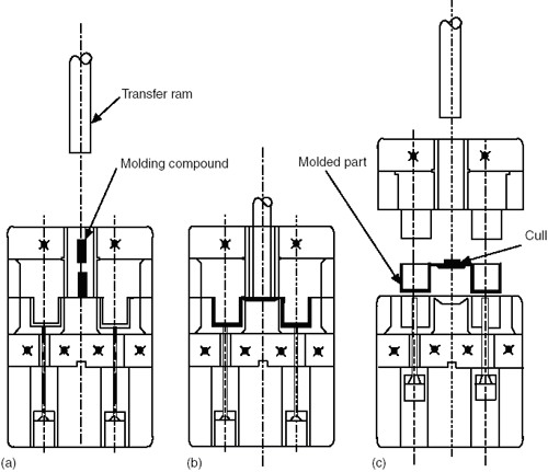
In transfer molding, the thermosetting molding powder is placed in a chamber or pot outside the molding cavity and subjected to heat and pressure to liquefy it. When liquid enough to start flowing, the material is forced by the pressure into the molding cavity, either by a direct sprue or though a system of runners and gates. The material sets hard to the cavity shape after a certain time (cure time) has elapsed. When the mold is disassembled, the molded part is pushed out of the mold by ejector pins, which operate automatically. FIGURE PP.3 shows the molding cycle of pot-type transfer molding, and FIGURE PP.4 shows plunger-type transfer molding (sometime called auxiliary raw transfer molding). The taper of the sprue is pot-type transfer is such that, when the mold is opened, the sprue remains attached to the disc of material left in the pot, known as cull, and is thus pulled away from the molded part, whereas the latter is lifted out of the cavity by the ejector pins (FIGURE PP.3c). In plunger-type transfer molding, on the other hand, the cull and the sprue remains with the molded piece when the mold is opened (FIGURE PP.4c). FIGURE PP.3 Molding cycle of a pot-type transfer mold. (a) Molding compound is placed in the transfer pot and then (b) forced under pressure when hot through an orifice and into a closed mold. (c) When the mold opens, the sprue remains with the cull in the pot, and the molded part is lifted out of the cavity by ejector pins. Another variation of transfer molding in screw transfer molding (FIGURE PP.5). In this process the molding material is preheated and plasticized in a screw chamber and dropped into the pot of an inverted plunger mold. The preheated molding material is then transferred into the mold cavity by the same method as shown in FIGURE PP.4. The screw-transfer-molding technique is well suited to fully automatic operation. The optimum temperature of a phenolic mold charge is 2400F + 200F (1550C + 110C), the same as that for pot-transfer and plunger molding techniques. For transfer molding, generally pressures of three times the magnitude of those required for compression molding are required. For example, usually a pressure of 9,000 psi (632 kg/cm2) and upward is required for phenolic molding material (the pressure referred to here is that applied to the powder material in the transfer chamber). The principle of transferring the liquefied thermosetting material from the transfer chamber into the molding cavity is similar to that of the injection molding of thermoplastics (described later). Therefore the same principle must be employed for working out the maximum area which can be molded梩hat is, the projected area of the molding multiplied by the pressure generated by the material inside the cavity must be less than the force holding the two halves together. Otherwise, the molding cavity plates will open as the closing force is overcome. Transfer molding has an advantage over compression molding in that the molding powder is fluid when it enters the mold cavity. The process therefore enables production of intricate parts and molding around thin pins and metal inserts (such as an electrical lug). Thus, by transfer molding, metal inserts can be molded into the component in predetermined positions held by thin pins, which would, however, bend or break under compression-molding conditions. Typical articles made by the transfer molding process are terminal-bloc insulators with many metal inserts and intricate shapes, such as cups and caps for cosmetic bottles.
FIGURE PP.4 Molding cycle of a plunger-type transfer mold. (a) An auxiliary ram exerts pressure on the heatsoftened material in the pot and (b) forces it into the mold. (c) When the mold is opened, the cull and sprue remain with the molded piece. |
|||
|